![]()
Recently visited
Featured Projects
Web Applications
Links
Other Projects
- Chainsaw Bike
- STM32F429 LCD Example
- My PHP Content Managing System
- PHP image handler
- Flyback-transformer driver
- Atari Punk Console
- Teensy - ESP8266 - Interface
- Charging station
- 4-bit Adder
Meta
Cellphone charging station circuit
Nov 2014My second paid project was to design the circuit for a cellphone charging station. It had lockers where you put your phone in and pay for charging time. It was my job to provide the central controlling circuitry. Into this circuit you plug in the phone-charging cables, the LED strips and the "Start"-buttons for each of the lockers.
The way the station works is that you insert money into the coin-accepter, select a free locker (lit with green LEDs), put your phone in it and lock it. To start the charging, you press the Start button of your locker and the LEDs will switch to red.
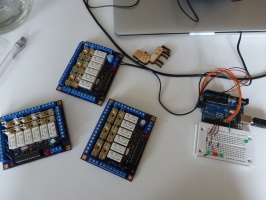
For the central processing unit, I used the atmega328p 8-bit microcontroller as I was most familiar with it and it suited the application. To control the loads, I used DPDT relays as they allowed for both LED-strips and the charger of a locker to be controlled with one IO-line.
The first few prototypes featured DIP parts and were hand-soldered.


